Modifications, hints, tips and technical information for the
Radioddity GD-77
dual band DMR digital handheld radio
Version 4.8 --- 18th January 2022 (FINAL: VK7JZA SK 17-JAN-2023)
Radioddity (pronounced as Radi-oddity or Ray-dee-odd-it-ee, not radio-ditty) produces the GD-77, an excellent little entry level dual band FM/DMR handheld radio that represents phenomenal value for money. I think it hits the sweet spot for the best ’bang-for-buck’, striking that perfect balance of affordability and features. Ham radio operators are often born tinkerers and like to tweak, customise and modify their equipment for even better utility, or just simply to personalise their equipment. Many such modifications have been listed on the GD-77 Facebook user page, which can make the information a bit hard to find. Presented here is a collection of modifications for the GD-77. Not all of these modifications are my own ideas, and credit has been given to the original author of the information as best as I have been able to find. Each modification is rated on a difficulty scale as follows:
Easy: no specialist skills required, easy soldering, minimal disassembly. If the thought of picking up a screwdriver makes you break out in a cold sweat, however, you might want to seek some assistance
Moderate: some skill required in soldering, electronics and/or computing, some disassembly needed. Any self respecting ham / electronics geek will be comfortable at this level.
Advanced: excellent soldering skills required, very good knowledge of electronics and/or computing, extensive disassembly.
Jason/VK7ZJA is sadly SK. I am providing this mirror of the last version to ensure this valuable information can be available to the community in the future. Page links have only been modified for mirroring, to remove references to possibly unreliable external file hosts, and to add these notices. No content modification has been performed and I will not be updating these pages. -NQ4T
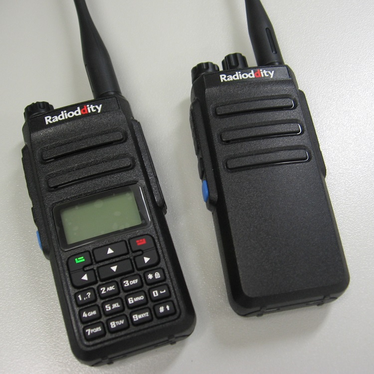
Protective leatherette case for GD-77
(Credit to Max Donoghue and others)
While there is no protective case made specially for the GD-77, it has been found that the Retevis RT3 / RT8 fit the GD-77 quite well, and the TYT MD-2017 case will also fit but is slightly too large, while cases for the TYT MD-380 will work OK too.
Cross compatibility of accessories for the GD-77
It has been found that many accessories for other radios are also compatible with the GD-77:
Charger cradle: TYT MD-380 / Retevis RT3 charger cradles also work for the GD-77
Programming cable: TYT MD-380 / Retevis RT3 programming cables also work for the GD-77, but note ANY of the Baofeng programming cables are not compatible
Belt clip: The belt clip used by TYT MD-380, Retevis RT3 and Baofeng UV-5R series also fit the GD-77
Multi-bay charger: There is a multi-bay charging station available for the TYT MD-380, this will also work for the GD-77 (Credit Joe Szperlak)
Antenna: Any decent quality single band or dual band antenna with a male SMA connection will work on the GD-77. NB: the connector on the GD-77 is a female SMA, so the antenna needs to be a male SMA connection. This is opposite to all the Baofeng handheld radios.
Protective case: as mentioned above, Retevis RT3 / RT8, TYT MD-380 and MD-2017 cases are all options.
Hint for the rubber side cover
(Credit to a user on Facebook GD-77 group, sorry I couldn’t find your name)
The speaker microphone rubber cover on the GD-77 can be turned 180 degrees to face down to lie flat against the side of the radio and be out of the way of any speaker microphone plugged in.
Change your GD-77 DMR ID on the fly
(Credit to Jason VK7ZJA)
Radioddity quietly introduced the ability to change your radio DMR ID on the fly from the keypad of the GD-77 without having to use a computer and programming cable. You will need at least firmware version 3.0.6 for this to work. Press [green menu button] then select Set > Radio Info > Radio ID > [green menu button] again and you will be able to edit your radio ID. The ID change will remain in place until you change it back, even after power cycling your GD-77.
Hint for longest battery life
(Credit to Jason VK7ZJA)
If you find that your freshly charged battery is not delivering around 8.3 or 8.4 volts after removing it from the charger, or your battery meter on the GD-77 is only indicating two-thirds with a freshly charged battery, or you see your battery charger flickering between red and green when nearing full charge - these are all signs of Li-Po cell imbalance within the battery. To partly reverse this situation, you should let your battery fully discharge, then fully charge for a few cycles. In order to keep your battery in good condition, it might be best to only occasionally let the battery fully discharge, before recharging it again. Don’t do this too often though, as that will shorten the life of the battery.
Battery meter & how it relates to actual battery life remaining
(Credit to Jason VK7ZJA)
You might see your GD-77 battery meter indicate it has two blocks of life left, but what does that actually mean? How accurate is that indication? The answer varies a little depending on your firmware version and how well used your battery is. From firmware version 3.1.6 and up the actual battery voltage to battery meter ’blocks’ remaining changed slightly to improve the spread of indications for the battery meter. Older and more well used batteries will have less capacity and appear to drain faster compared to new batteries as well.
Compared to firmware versions 3.1.5 and earlier, the battery meter in firmware version 3.1.6 and up will appear to indicate the battery draining faster, but that is just because the battery meter calibration has been re-jigged.
The following table was produced by reading the actual voltage presented to the GD-77 battery terminals with a variable regulated power supply and measured with a high quality Fluke multimeter. The percentages given for battery capacity remaining are very approximate only:
| Firmware versions |
Full (three blocks) |
Two blocks | One block | None | Recharge (lightning bolt) |
Radio auto turns off |
|---|---|---|---|---|---|---|
| v3.1.6 and over | 8.14 volts and over over 90% |
7.51 - 8.14 volts 55-90% |
6.90 - 7.51 volts 3-55% |
6.57 - 6.90 volts 1-3% |
under 6.57 volts under 1% |
5.40 volts |
| v3.1.5 and under | 7.88 volts and over over 80% |
7.25 - 7.88 volts 10-80% |
6.62 - 7.25 volts 2-10% |
6.32 - 6.62 volts 0-2% |
under 6.32 volts dead flat |
5.40 volts |
Known power up sequences
There are several different functions that you activate by holding down keys while simultaneously powering up the GD-77. SK1 is the smaller black button immediately below the PTT and SK2 is the smaller blue button beneath SK1.
- SK1 and 1 : Memory reset, confirm by pressing green menu key
- SK1 and 2 : undocumented, RF test. Quick TX test probably used at the factory. Caution: will TX a carrier on last selected memory channel or VFO frequency, and it will ignore any TX inhibit!
- SK1 and 7 : V3.2.1 firmware and above only, toggle between unlocked and locked frequency ranges / VFO disabled. Confirm by pressing green menu key
- SK1 and SK2 : Firmware update mode, top panel LED will light up green
- SK2 and 3 : undocumented, appears to do the same as SK2 and 9 below?
- SK2 and 9 : Softer reset than a full memory reset, top panel LED will flicker orange during reset
- SK2 and green menu key and # (up) keys : DMR ID loading mode using ActiveClient.exe (no special indication visible to show when activated)
- SK2 and green menu key and * (lock) keys : undocumented, allows reading & writing of all flash memory addresses (no special indication visible to show when activated)
Different power supply for the charging base
(Credit to Jason VK7ZJA)
Can I use my shack 13.8 volt power supply to power the charging base for the GD-77? Yes you can, the charging base has a voltage regulator inside and it will accept any voltage between about 10 and 16 volts quite safely.
Converting different versions of codeplugs
(Credit to Colin G4EML)
As the CPS software and firmware was upgraded to later versions, the codeplugs from earlier versions became incompatible i.e. codeplugs are not forward or backward compatible. This means that you would have to re-create your codeplugs every time you upgraded to a newer version. Colin G4EML has created a codeplug converter which will help make this process much easier. Download it from:
http://www.gb3gf.co.uk/Files/GD77-CSV.zip
Why won’t encryption work between GD-77 and other radios?
People have found, to their disappointment, that encryption used on the GD-77 and other radios is not compatible. How can this be, DMR is supposed to be a standard, so shouldn’t all radios therefore be compatible? Well, no. Even though DMR is an ETSI standard, that standard doesn’t specify the encryption method to be used - this is left free for each manufacturer to implement as they like. This is almost guaranteed to result in encryption between different radios being incompatible.
The GD-77 has a ALPU-MP series 128 bit Advanced Encryption Standard (AES) dedicated encryption & decryption IC, which may be used for the encryption of DMR voice frames - yet to be confirmed. If that is the case, at least the GD-77 uses a known standard encryption system and just maybe at some point, might become compatible with other radios also using AES?
More reliable DMR repeater operation. Easy
(Credit to Roger VK3KYY and Colin G4EML)
If you are right on the edge of coverage of your local repeater and not able to access it with your GD-77 in DMR mode, there is a setting that can help. By default, the GD-77 CPS is only set to try to access the repeater and listen for the ’access granted’ reply from the repeater just the once. You can increase the number of retries to improve your chances of accessing the repeater if your signal is marginal. I recommend setting the following:
At the left side menu tree, double click on Signalling System.
On the new window that opens up, set TX Wakeup Message Limit to 3 and TX Sync Wakeup TOT [ms] to 150
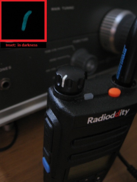
Volume indicator visual enhancement. Easy
(Credit to Jason VK7ZJA)
As the GD-77 is delivered from the factory, there’s no easy to see visual indication as to where the volume knob is pointing, so you can’t quickly identify how loud the radio is turned up to at a glance. There is a nice little hollowed out groove or recess in the volume knob, perfect for filling with paint. But why settle for just any ordinary paint? Using a fluorescent paint that glows in the dark will help you see the volume setting after the sun goes down. I selected a paint that dries to an off-white colour for best contrast in the daytime, but glows a light green in the dark which is the colour the human eye has peak visual response to. Using the point of a toothpick as a paintbrush, I painted a thin layer of paint within the volume knob’s groove, let it dry and repeat with more layers of paint until the paint built up to be flush with the rest of the knob.
Custom callsign labels from KC8GL. Easy
We hams love to customise our equipment. That’s what this page is all about. Take your GD-77 to the next level with these superb custom laser etched labels from Greg KC8GL. Professional in appearance, priced very keenly, and delivered to you fast - Greg is always happy to discuss your needs and answer any questions you may have. Greg also does some lovely cherry wood callsign display plaques. I highly recommend them! Visit: https://sites.google.com/view/kc8gl/radioddity-gd-77-call-sign-sticker
Screen scratch protection. Easy
(Credit to Jason VK7ZJA)
To save your screen plastic lens from getting scratched up, you can repurpose a cheap cell / mobile phone screen scratch protection film for the GD-77 screen. Obviously you will need to cut it down to size to suit, which can be fiddly to do, but worth the few minutes effort to keep the screen scratch free.
If your screen is already scratched, I highly recommend a product called PolyWatch, a plastic & acrylic polish that is meant for stratch removal from watch crowns, but works really well for display lens scratch removal too.
Alternate / custom firmware for GD-77. Easy
Unfortunately, the OpenGD77 project has now been shut down due to a legal challenge by a ham operator.
Another project to keep an eye on is OpenRTX, using a new digital mode called M17. It does not appear to be compatible with DMR, and as such can not be used with DMR networks like Brandmeister and the like. However that may change in the future... it will be interesting to see where the project goes.
Sitting up straighter. Easy
(Credit to Tony Slater)
If you hadn’t already noticed it, when standing up on a flat surface the GD-77 has a tendency to tip over forwards. That’s because the radio’s feet are a little off level causing it to have a slight forward lean. The solution is to shorten the feet on the battery only. Take off the battery, and to be safe, tape over both sets of battery contacts. Use a flat file to file down the feet on the bottom of the battery until they’re almost flush with the rest of the case. There is no need to do this to the feet on the radio itself. Remove the tape and reinstall the battery. Another method suggested is to use a hobby knife / scalpel to cut the battery feet off nearly flush. Now you can enjoy a radio that is a little more stable when standing up on a flat surface.
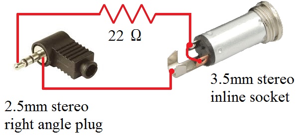
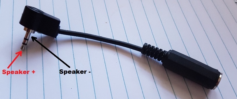
Headphone adaptor. Easy
(Credit to Jason VK7ZJA)
Here is a simple and easy to make adaptor so you can listen to the GD-77 with normal headphones. You’ll need a right angle stereo 2.5mm audio plug, a stereo 3.5mm audio socket, a short length of shielded audio cable and a 22 ohm 1/4 watt resistor. Connect them up following the wiring diagram below, and you’re good to go. I also filled the right angle audio plug with hot melt glue to secure the connection and give the connector a bit more solidity.
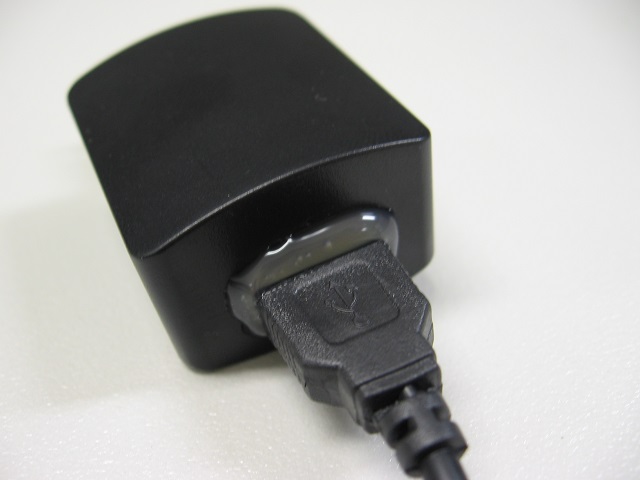
Prevent the GD-77 ’USB’ charger from being used with, and possibly damaging, other devices. Easy
(Credit to... lots of people who all came up with great ideas!)
The charger that has been supplied with a lot of GD-77s uses a USB style connector. Genuine USB devices are powered by 5 volts, but the GD-77 charger puts out 12 volts. If someone were to accidentally connect a genuine USB device to the GD-77 ’USB’ charger, it could cause damage to the connected device. A simple and foolproof remedy to this is to use hot melt glue to permanently fix the GD-77 charging base cable into the GD-77’s charger ’USB’ socket, as in the below picture.
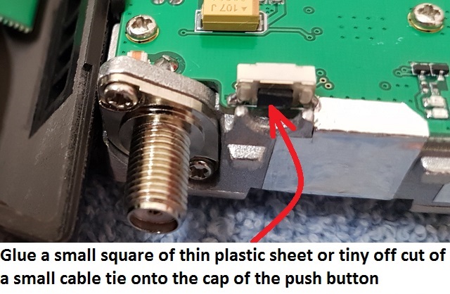
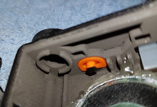
Make the top panel orange button easier to press (early versions of GD-77). Easy, with some disassembly.
(Credit to Jason VK7ZJA)
The top panel orange button is intended for use as an emergency button, and as you might expect, it has been designed to be a little difficult to push to prevent accidental activation. It really does need firm positive pressure to make it work. At least, that’s the way it is on early build versions of the GD-77; later versions seem to have made this button a little easier to push. There is nothing to say that you can re-use that button for a regular function, the emergency feature isn’t hard wired to that button, and can be reprogrammed as you like. In that instance, it would be nice to be able to press the button easily. If you find yours is a bit tricky to press, here’s a simple mod that will help. All we are going to do is raise the level of the push button on the PCB so that it is ’taller’ and requires less pressure on the orange rubber button to activate. To disassemble the radio, begin by removing the battery and antenna, and gently pull off the volume knob. Use a ring spanner or fine needle nose pliers to undo & remove the ring nuts that hold in the volume control and antenna SMA socket. Use a T8 torx driver to undo and remove the bottom two screws at the back of the radio. You’ll now be able to lift out the metal chassis, lifting from the bottom first, and pulling downwards out of the plastic shell. Be careful, there is a ribbon cable connecting the front panel and main board, which could be damaged if you separate the two too far apart. This ribbon cable will need to be removed from it’s connector to enable more access to the insides of the radio. Using a very fine flat blade jewellers screwdriver, lever up the ’collar’ of the connector sides by little ’tabs’ that protrude slightly at the sides of the connector. The collar will swing upwards and release the ribbon cable, gently pull it out of the connector. The wires connecting to the speaker can remain in place, but you do have to be gentle with them too, otherwise they can break off. Now that you have access to the inside of the radio, find the push button on the top edge of the radio PCB. Find a tiny bit of thin flat plastic and cut it to roughly the same size as the plastic push button, and use a very tiny dob of super glue to attach the thin plastic to the push button. Be careful not to use too much super glue as any excess could run down the push button and glue it so that it can’t be pushed. I used a tiny off cut of a plastic cable tie cut to about 3mm square and glued that on to the top of the push button. Once the glue has well and truly dried, it’s time to reassemble the radio. The ribbon cable can be inserted to it’s connector - make sure it’s as far in as it will go and sitting square in the connector, and then flip the retaining ’collar’ back down to clamp the ribbon cable in the connector. The top panel orange button should now be much easier to press and activate.
Modify a speaker microphone to keep out DMR pulsed RF feedback. Moderate
(Credit to Owen Duffy VK1OD for this)
If you have a speaker microphone that you like, but is affected by RF feedback from DMR’s pulsed RF getting back into it, causing your transmitted audio to become distorted, you can perform modifications to reduce or even eliminate this problem. I have carried out the modifications, adding a SMD capacitor across the speaker microphone electret element, and adding a SMD inductor in line with the positive line of the electret element, and confirm it works very well indeed. See Owen’s mods at:
http://owenduffy.net/blog/?p=9326
Prevent the GD-77 charger from overcharging your batteries. Moderate
(Credit to Wolfgang DL4YHF for this)
The battery supplied with the GD-77 is a lithium ion type, which like to be charged to a maximum voltage of 8.40 volts. Any higher voltage begins to reduce the long-term life of the battery. Depending on individual component tolerances, sometimes the voltage supplied to the battery by a GD-77 charger can vary from unit to unit a bit, and if you find your charger supplies any more than 8.40 volts, in the interests of battery longevity, it would be good to modify your charger base to get as close to 8.40 volts as possible. Some charging bases have been shown to put out as much as 8.60 volts. A modification from Wolfgang DL4YHF adds a resistor to bring this voltage down a tiny bit. You might have to play with the value slightly to get as close to 8.40 volts as possible. If your unmodified voltage is particularly high, say 8.60 volts, then try starting with 390k ohms soldered in parallel with R4. If your unmodified voltage is not all that high, around 8.50 volts, then a 470k ohm or 560k ohm resistor might be a good place to start. The modification Wolfgang presents is for the Retevis RT3, which is identical to the TYT MD380; the GD-77 charging base is the same too. See all the detail, and the theory behind this modification at:
http://www.qsl.net/dl4yhf/RT3/
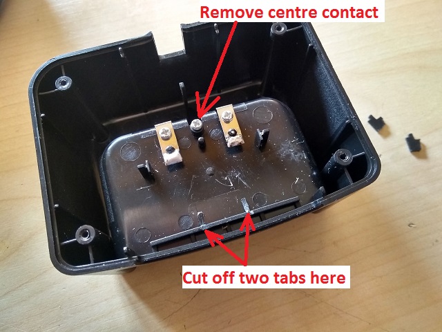
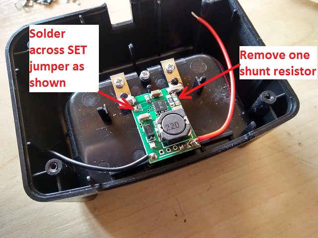
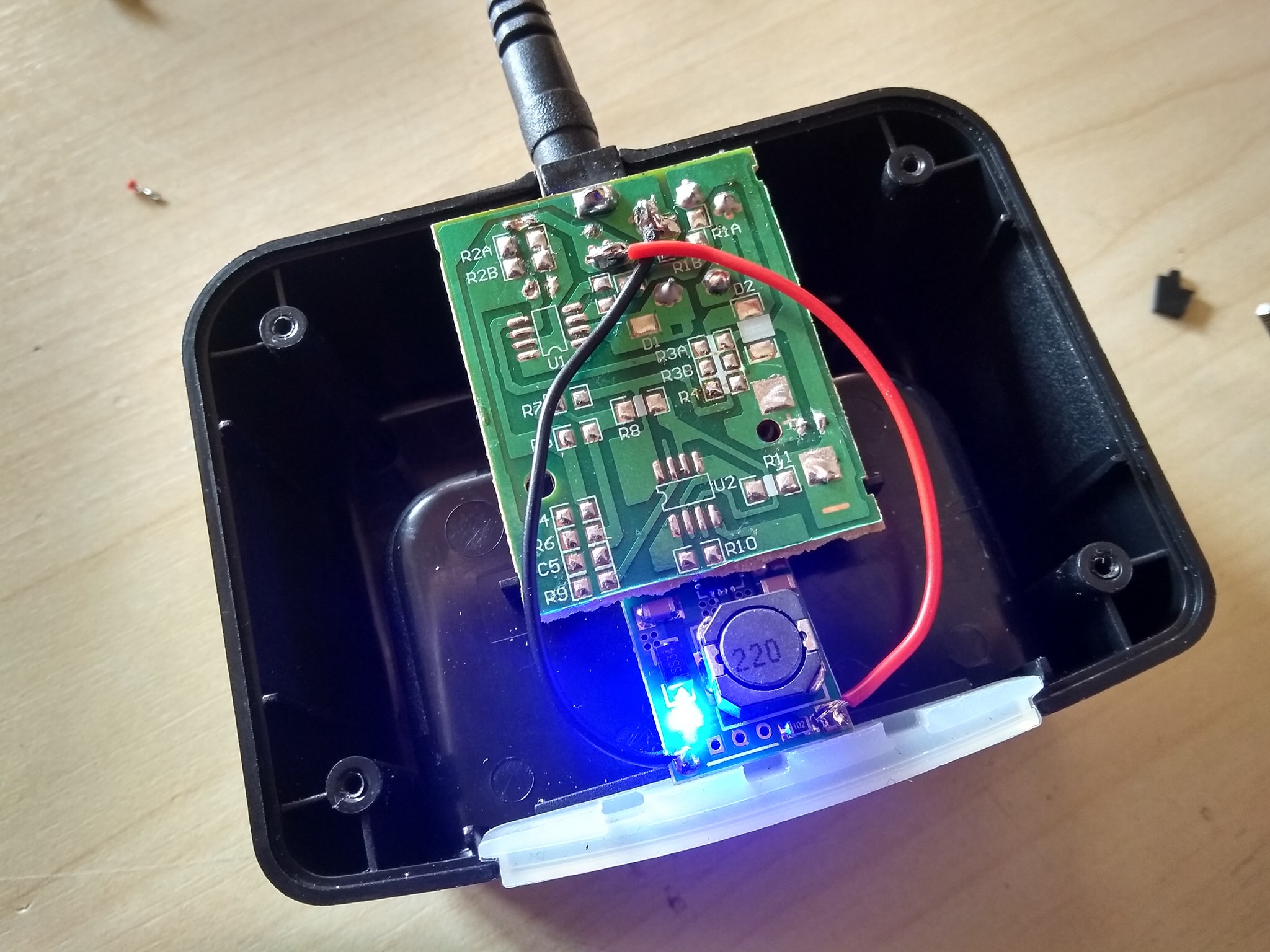
Faster charge for the GD-77. Moderate
(Credit to Jeffrey Vandenbroucke ON3AD)
On AliExpress or eBay, you can buy Li-ion cell charger modules (TP5100) at very low cost, under $2. You have to install a small solder bridge to configure the module for series charging of two Li-ion cells and also remove one 0.1 Ohm shunt resistor to lower the charging speed from 2Ah to 1Ah. Then cut away part of the old PCB to keep some mechanical support for the DC jack. You could also use hot melt glue to hold in place a new DC jack alone, without having to re-use the old charger PCB. Then remove the two little front black plastic tabs as indicated in the picture and the middle unused battery contact. Next: solder the charger board directly to the terminals. Remove the old charger components with hot air gun / hot air paint stripper, the old charger PCB is now only used to hold the DC input jack in place. Hook up the new board while observing the polarity. You now have a great Li-ion charger with an 8.4V cut off, and starts charging at 8.2V again, and it looks factory default. Charging is now done at 1Ah which is 0.5C in relation to the actual cell; well in the safety margin. You won’t be able to use the original GD-77 ’wall wart’ power supply, as it is only rated to 500mA. Replace it with a 12 volt (or any voltage between 10 and 15 volts) supply that can supply 1200mA / 1.2A. The new charger will indicate red for charging and blue for battery full. Enjoy your non-QRM quick charger.
Another faster charge modification for the GD-77. Moderate
(Credit to Ronan EI4KN)
Ronan found an intelligent 8.4 volt Li-ion charger that can connect directly to the battery cells being charged, for less than 5 Euros / USD $4, which includes delivery. It comes with your choice of electrical plugs to suit US, UK, European and Australian mains wall sockets, has a charging status LED on the front, and charges the GD-77 battery at a (still safe) rate of 1 amp, or just under three hours from flat to full. See Ronan's webpage here for how he did this:
https://ei4kn.wordpress.com/2017/06/28/retevis-rt3-charger-modification/
And the intelligent charger is available here: https://www.aliexpress.com/item/5-5-2-1mm-DC-8-4V-1A-Smart-Intelligent-Charger-Li-ion-LiPo-Battery-AU/32712256811.html
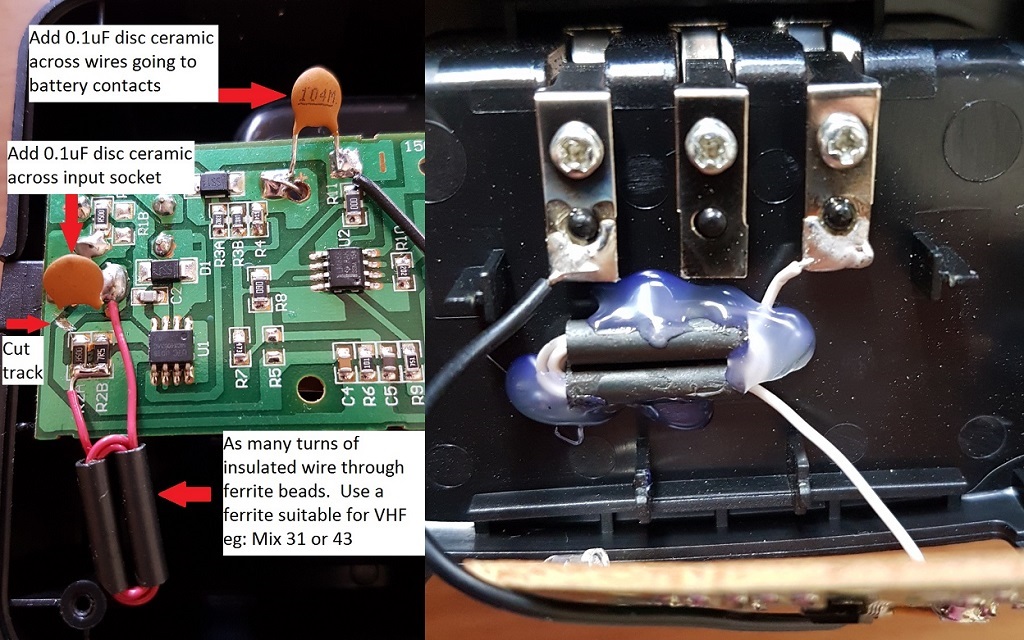
Reducing RFI from the charger base. Moderate
(Credit to DL4NO)
Weak VHF signals can be masked by RFI noise from the charger while the GD-77 is being charged in it. The following modifications will reduce the RFI considerably. Open up the charger base and locate the solder pads where the input socket attaches to the PCB - solder a 0.1uF disc ceramic or other low RF impedance capacitor type across those solder pads. Similarly, place a 0.1uF disc ceramic capacitor across the solder pads that go to the battery contacts. Finally, remove the wire from the PCB that goes to the positive battery contact - it’s the bare tinned wire that goes through a hole in the PCB - and replace it with a longer wire that has been wound through a ferrite bead a number of times. The ferrite mix should be good for VHF attenuation, and any type of bead style could be used: toroid, single, double or multi-hole bead etc. Visit:
http://www.dl4no.de/thema/gd-77.htm
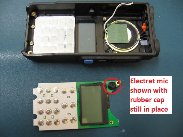
Changing the electret microphone element. Moderate
(Credit to Razvan Marin)
One way to change the audio qualities of your transmitted audio is to change the electret microphone element. You’ll find the electret microphone on the PCB that has the LCD display and front panel button keypad. It’s not too hard to de-solder the two pins and replace the electret element with another compatible type such as the POM-3542P-R. Razvan found he had louder transmit audio and more natural sounding voice with this replacement, however my results were a little different. Transmitted audio was more bassy yet sounded less ’punchy’ as well as being considerably softer with the POM-3542P-R. It seems like results will vary from individual to individual and radio to radio, but from my experience, I don’t recommend it.
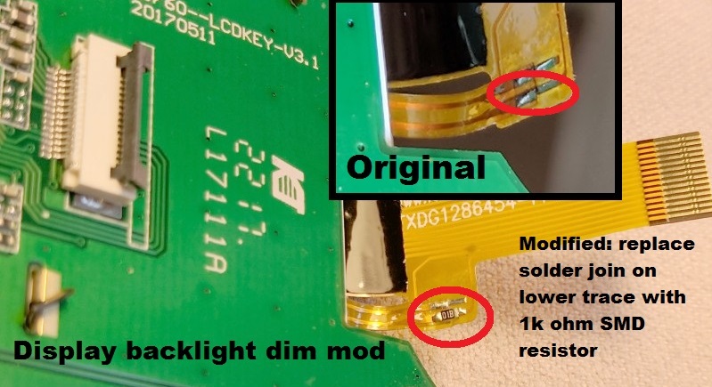
Dim the LCD back light. Moderate to Advanced
(credit to Radioprofi)
If you find the original LCD display back lighting to be too bright, you can permanently dim it by adding a surface mount (SMD) 1k ohm resistor in line with the back light at a convenient flexible ribbon cable join. De-solder the join between the ribbon cable contacts on just the one line, make sure they won’t make contact by carefully trimming the ribbon contact back a tiny bit, then join the ribbon traces with a 1k ohm SMD resistor, as per the below photo.
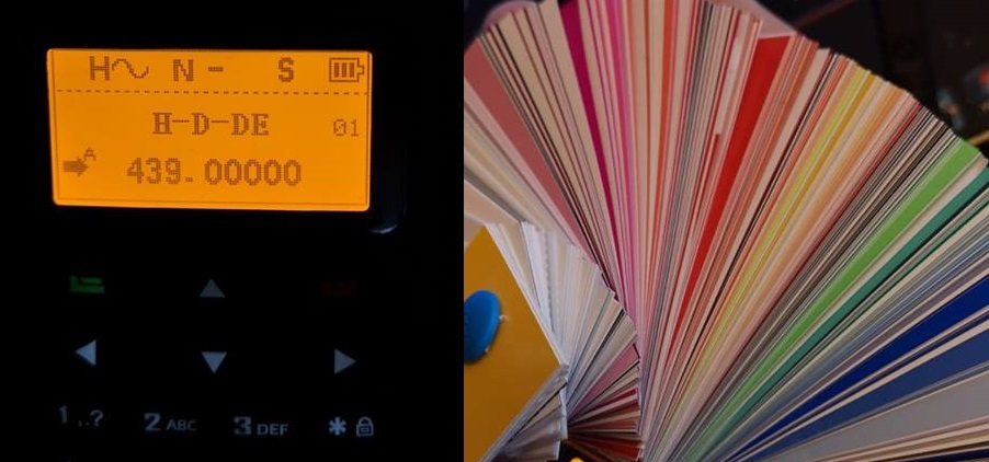
Change the LCD colour. Moderate (some disassembly)
(credit to Torsten DO5AD)
Torsten had the brilliant idea of using cheap LEE lighting / photography flash filters over the LCD, sandwiched in between the LCD frame and the front clear display lens to change the colour of the LCD. You can find the LEE filter ’designer edition’ swatch collection on eBay at reasonable prices, these are an economical way to buy a very wide selection of coloured plastic filters. Now you can change your display to a blue, green, orange, pink, red or any other colour in between. Other manufacturers have similar items, too and may be easier to obtain in locations outside the USA or Europe. Torsten disassembled the front panel of his GD-77 to get access to the LCD, cut the filter material to size and taped it to the metal LCD frame and reassembled the radio. The result was a clear, sharp and easy-on-the-eye display. This photo shows a LEE 780 ’golden amber’ filter fitted. The result looks fantastic!
Introduction to hex editing. Moderate
Hexadecimal - more commonly abbreviated to just ’hex’ - is a system of counting with sixteen symbols. We humans are used to counting from one to ten with our ten symbols we call numbers, those being 0-9. If we want to go above 9, we join two numbers together e.g. 1 and 0 to be 10, and so on. Hexadecimal begins with 0 and goes up to 9, but instead of moving on to 10, hexadecimal uses letters A through to F, so A in hex would be 10, B=11, C=12 and so on up to F which is equal to 15, then hex "10" is equal to 16, 11 in hex = 17 and so on. Once 19 in hex is reached, the next number is 1A. Get the picture? Have a play around with a scientific calculator to convert hex numbers to decimal numbers, and you’ll soon see how it all works.
OK, so why hex? As you probably know, computers use digital logic circuits which have just two values: on and off. These can be thought of as a 1 or 0, and computers ’talk’ with lots of 1s and 0s - that’s called binary. For us humans to try and make inputs to a computer in binary with just 1s and 0s would be mind-numbingly tedious, but using hexadecimal is a compromise. You’ve probably heard the term ’byte’ before, and it turns out that two hexadecimal numbers fits perfectly into a byte. So 00, 3A, D2 and FF (all examples of hex numbers) can be represented with one byte of memory.
If you were to open a new text document with simply the word "HELLO" in it, and save that text document, you could open the text document in Notepad and edit it at a later time. But that’s not the only way you can edit this text document. By opening the text document in a hex editor application, you can edit the document in it’s raw form as it is stored on your hard disc. What you would see is the word HELLO represented by it’s hex numbers: 48 45 4C 4C 4F. Now lets say you want to change HELLO to APPLE instead. In the hex editor, you would change those hex values to 41 50 50 4C 45, and then save the file.
The advantage of hex editing a file is that it doesn’t matter what created the file or what the file contents are, they all get stored on hard disc the same way, and with hex editing you’re editing the raw data and there are no limitations to making those edits, rather than any artificial limits a program might impose.
One more thing to know before moving on to your first software modification is to know about the concept of little-endian formatting. Little-endian formatting is listing a value with it’s least significant bytes first. Take a number like 490 for example. First break the number up into two bytes: 04 and 90 (add a zero in front of the first number if it’s not already two digits). Now simply reverse the order of the bytes, so that is 90 04. That is little-endian format of (0)490. Another example with a bigger number: 12345678. Broken up into bytes, that’s 12 34 56 78. Now reverse the order of those groups: 78 56 34 12. Not hard, is it? Little-endian formatting can be equally applied to decimal or hex numbers, simply break the number down into two digit groups (i.e. bytes) and then reverse the order of the groups.
To make edits in hex, you’ll want to use a hex editor. It’s just like a word processor, only it edits in hexadecimal. I recommend using a hex editor called HxD. It’s free to download at:
https://mh-nexus.de/en/downloads.php?product=HxD (about 860kb)
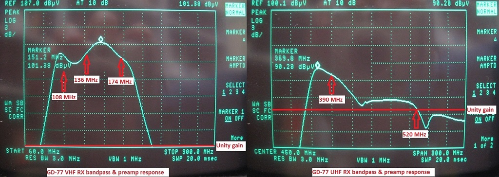
Out of band frequency entry. Moderate
(Credit to Roger VK3KYY & Jason VK7ZJA)
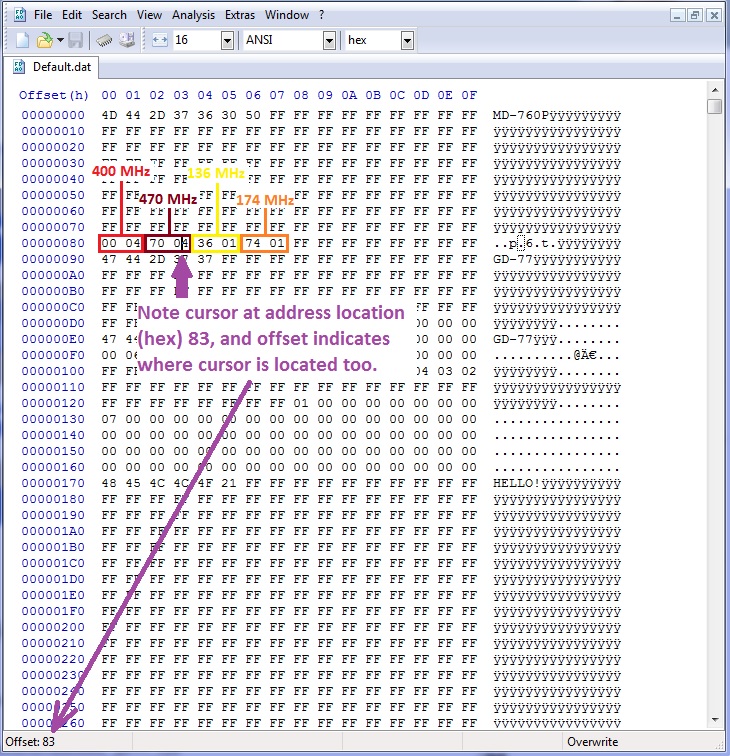
As delivered, the GD-77 covers 136-174 and 400-470 MHz. Users in some parts of the world make use of spectrum outside these limits, and it would be desirable to be able to expand the frequency limits permitted for entry. Ultimately you can increase the frequency limits to about 130-178 and 390 to 520 MHz. Minor variations due to hardware manufacturing tolerances can be expected, so ’your mileage may vary’ as they say. Some people have reported the GD-77 will self-reset if any frequency below 136 MHz is entered; I’ve not had that issue myself. However, the GD-77 definitely will self-reset if you try to expand the upper UHF frequency beyond 520 MHz. Listed here are three methods you can use to expand frequency ranges, and you may choose to combine the first two methods. Method 1: This method works best if you have an existing codeplug that you want to reuse and expand the frequency range that is attached to the codeplug. Find and make a copy of default.dat file, and rename the copy something like originaldefault.dat. Next, load your default.dat file into a hex editor and find your way to the bytes at addresses (hex):
80, 81: Lower range UHF frequency, little endian formatted. Would normally have the values 00 & 04 respectively for 400 MHz
82, 83: Upper range UHF frequency, little endian formatted. Would normally have the values 70 & 04 respectively for 470 MHz
84, 85: Lower range VHF frequency, little endian formatted. Would normally have the values 36 & 01 respectively for 136 MHz
86, 87: Upper range VHF frequency, little endian formatted. Would normally have the values 74 & 01 respectively for 174 MHz
So for example, if you wanted to increase the upper end of the UHF frequency coverage to 490 MHz, you would change address 82 from 70 to 90. Take a look at the screenshot below from HxD for the example of what you would see:
Now make the same edit to any of your codeplug .dat files you have previously saved. Once this edit to your codeplugs have been made, you can use the CPS software to enter and edit frequencies to your new specified limits. There is one catch, however: you should never look at the ’Basic Information’ page in the CPS software after making this edit. If you were to do so, the software would reset any programmed frequency outside of the original 136-174 or 400-470 MHz limits back to a default frequency.
Method 2: This method works best if you are starting new codeplugs, but it won’t allow any existing saved codeplugs to be expanded - you will need to apply method 1 to any of your previously saved codeplugs. Here you are editing the frequency limits that are hard-coded into the CPS software, so you’ll be hex editing the .exe file. When doing this, it’s always best to make a copy of the .exe and work on the copy. Lets use the example of extending the lower UHF coverage down from 400 to 395 MHz. Unlike the .dat files where the frequencies limits are stored in decimal (albeit in little endian format) the .exe software doesn’t.
1) Convert 400 into hexadecimal, which results in 0190.
2) Convert that into little endian format: 90 01.
3) These are the values you need to search for in the .exe file with HxD. You might find a few locations where the values 90 & 01 are found together, so try editing each location and see if this has the desired effect. If not, just change these locations back to 90 & 01, and edit the next instance of these values that are found. For V3.1.1 CPS.exe, you’ll find that addresses (hex) 56136 & 56137 hold values 90 & 01, and are the correct locations to edit for the lower UHF limit (other versions of the CPS may hold these values at different addresses).
4) To change to 395 MHz: convert 395 to hex = 018B. Now little endian format = 8B 01. So replace the value 90 with 8B and you can leave value 01 as is.
5) Save the edited file, and test.
To make life a little easier, the default frequency limits are represented by the following:
136 MHz in hex = 0088, then little endian format = 88 00.
174 MHz in hex = 00AE, then little endian format = AE 00.
400 MHz in hex = 0190, then little endian format = 90 01.
470 MHz in hex = 01D6, then little endian format = D6 01.
They’re the byte pairs you should search for using HxD while editing the .exe file. Save the file, and then test to make sure it works.
Method 3: This method is the easiest of the lot, but you won’t learn anything new by doing this (boo!) Courtesy of Roger VK3KYY, you can download the ’Community Edition’ of GD-77 CPS which has the frequency limits already opened up in the software, plus many other advantages besides. The Community Edition CPS integrates the DMR ID database uploading function and the ability to read & edit RF alignment data, as well as other nice user tweaks. Download the CE CPS from:
http://www.rogerclark.net/reset-you-links-to-the-gd-77-cps-downloads/ (974kb)
Cross-band frequency entry & operation. Moderate
(Credit to Roger VK3KYY & Jason VK7ZJA)
You can use the GD-77 for FM crossband use, operation won’t be in full duplex mode, only half-duplex is possible. But the stock CPS software won’t allow cross-band frequency entry for memory channels, you will have to get busy with hex editing of the channel data in your .dat file.
There are two caveats, however: RF output power is roughly halved during cross-band operation, and cross-band operation in DMR mode is not possible with the GD-77 (this is because the GD-77 uses the RF alignment data for the RX frequency of the channel for both RX and TX, assuming they will be in the same band; the alignment data for VHF can be ’off’ enough on UHF for DMR to become distorted and vice versa)
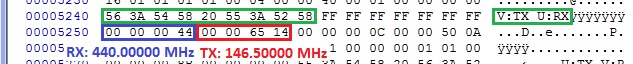
Follow the below example, where we program a cross-band channel entry with a receive frequency of 440.000 MHz and a transmit frequency of 146.500 MHz:
1) In the CPS software, program a channel with a unique name, here the channel name is "V:TX U:RX". Don’t worry too much about what frequencies you enter, as we’ll edit them in the next few steps. Save the .dat codeplug.
2) Open your .dat file in HxD, and search for the text of your unique channel name on the right half of the display. Here you can see the channel name inside the green box.
3) Using little endian format, enter four bytes for your desired receive frequency as seen in the blue box.
4) Again using little endian format, enter another four bytes for your desired transmit frequency as seen in the red box.
5) Save the edited .dat file. You can now re-load the codeplug in the CPS software and it will display the frequencies OK - just don’t try to edit the channel from this point onward, otherwise the CPS software will get upset and reset your work.
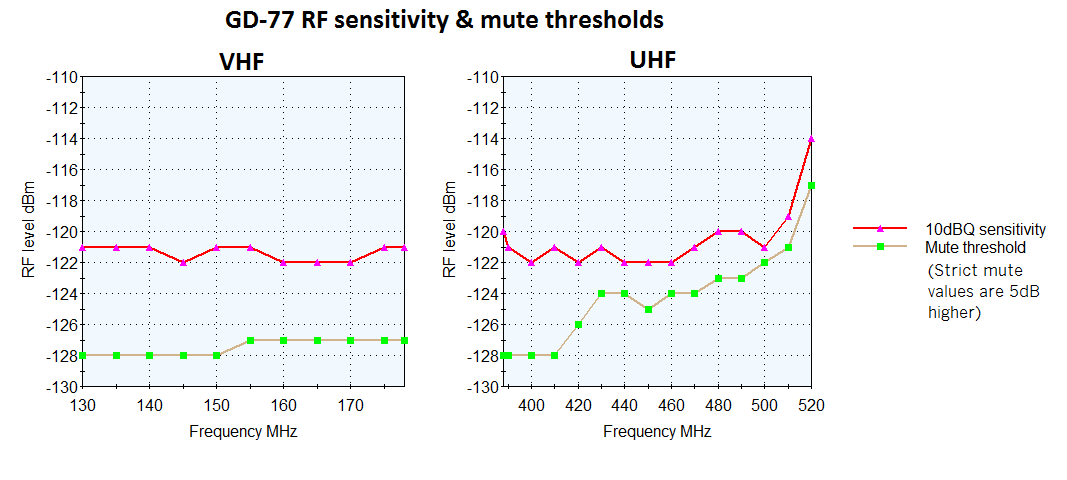
Is 220 MHz operation possible? Moderate
(Credit to Jason VK7ZJA)
You may have noticed that the GD-77 uses a ’radio on a chip’ RDA / AT1846S which according to it’s datasheet covers VHF 134-174 MHz, UHF 400-520 MHz... and also 200-260 MHz. In practice, the chip is actually capable of a little bit more coverage either side of the specified limits, your mileage may vary a bit in this regard. So does that mean the GD-77 will also operate on the (USA only) 222 MHz ham band as well? Well, yes and no.
Yes, the GD-77 will definitely receive on this band, typically around 195 to 285 MHz, but sensitivity will be poor due to the RF preamps being designed and tuned for VHF and UHF, not for 220 MHz operation. Here you can see a sensitivity plot - it’s nothing spectacular, but will allow you to hear stronger signals in this band.
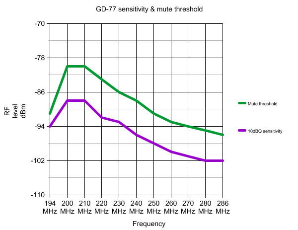
But what about transmit? This is a firm NO! Do not try to transmit with the GD-77 on 220 MHz. The reason is that the RF power amplifier stage is not designed for 220 MHz, and the PA stage is trying to dump RF power into a bandpass filter that is horribly mismatched for that frequency. You will risk burning out the electronics if you transmit here. Not only that, but actual RF power put out at 220 MHz is very low, only a few milliwatts. DMR 4FSK and FM deviation levels are all over the place, so the radio won't be transmitting a very clean signal at all. As if that wasn’t reason enough, the second harmonic output from attempted transmissions here is several watts, and you could be causing severe interference to other services in the UHF band. Just don’t do it!
So, if you’d like to add a bonus 195-285 MHz receiver to your GD-77, all you need to do is set your lower UHF frequency limit to 195 MHz using the above methods for out of band frequency entry. Roger’s Community Edition CPS will also allow this as well.
Lost program codeplug password / corrupt codeplug password recovery for GD-77 (or RD-5R): Moderate
(Credit to Jason VK7ZJA)
If you’ve lost the password for programming the codeplug, or it has become corrupted, any attempt to read or write the radio will result in failure and there’s not much you can do until you do obtain the password. Here is a way to read the password or delete it.
1) Download Roger’s GD-77 Flash Manager (works with the RD-5R for this process, too): Download GD-77 Flash Manager here (61kb)
2) Connect your GD-77 or RD-5R with it’s programming cable, turn it on normally (do not hold any buttons while powering on). Don’t start the CPS software, start up Flash Manager instead. Respond ’yes’ to the warning message.
3) In the input boxes of Flash Manager, enter Start address (hex) of 00, then enter Length (hex) of 200. Hit the ’Read’ button.
4) In the main area of the display, next to address 00000100, the eight bytes there are your program password in hex. To the right side of the display on that same line is a text representation of the program password, it can be up to 8 characters long.
At this point, you have two choices:
A) You can write down the password and enter it when requested in to the CPS, and then once you have the codeplug read or written, remove all trace of the program password, it’ll be under General Setting, Program Password.
B) You can overwrite the first byte of the password with hex characters FF to effectively erase the password. If there are non-standard characters in the password that you can’t enter via the computer keyboard, this is the only option that will work. Click on the hex characters at address 00000100 and enter a single FF, then set the Start address (hex) as 100, Length (hex) as 20 and click the Write button. The codeplug program password is now deleted.
GD-77 tuning & alignment information. Advanced
(Credit to Jason VK7ZJA)
RF tuning and alignment data is stored as ’soft’ calibration values in flash memory which you can edit. You can tweak things like microphone gain, RF output power, signal strength meter sensitivity, mute/squelch levels, fine tune frequency setting, deviation levels and more. This has it’s own page, visit:
GD-77 Tuning & alignment information
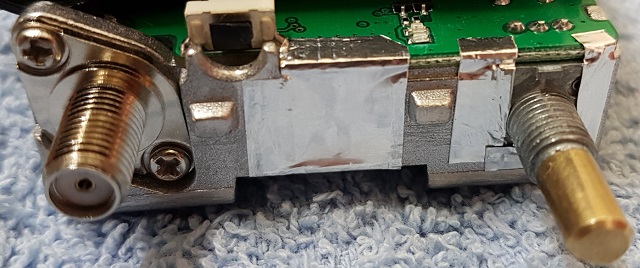
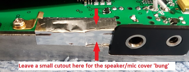
Improving RF shielding on the GD-77. Advanced (extensive disassembly)
(Credit to Jason VK7ZJA)
This modification is pretty hard core, and the improvements are not dramatic. That said, there are three parts to improving RF shielding of the GD-77.
RF shielding nickel spray paint: If you look inside some cellular mobile phones or portable two way radios, you will sometimes see a coating of paint on the inside of any plastic parts. This paint could be black, brown, pink, grey or silver, and they all have a similar job: they’re conductive and add a thin layer of RF shielding to the electronics inside. Electrolube’s NSCP400H nickel spray paint is sold by Element14 (Farnell), or you might be able to find alternative products from other suppliers. You’ll need to follow these general steps:
1) Completely disassemble the GD-77. You need a bare plastic shell with the keypad and LCD display, speaker, orange top button and the plastic ’light pipe’ for the top mounted TX/RX LED removed.
2) Use masking tape to cover every surface that you don’t want the nickel spray paint to go. That not only includes all the visible exterior parts, but also many interior areas as well. Cut out a circle of cardboard to fit on the inside of the speaker grille, and also cut out a rectangle of cardboard to the same size as the LCD clear display window. Also block up any openings such as the holes where the keypad goes with cotton wool - I use craft work decorative soft balls for this, and it works well. This job of masking every surface you don’t want covered by the paint is fiddly and tedious in the extreme, but is necessary because the spray paint will go everywhere, trust me!
3) Nickel spray paint is known to be rather hazardous. You will want to do this job outside, and on a calm wind free day. Wear goggles, dust mask, long sleeve shirt and rubber gloves. Place the masked up shell onto a piece of scrap cardboard and use good spray painting techniques to apply a thin coat of nickel spray on the inside of the GD-77 shell. The spray will look uneven as you apply it, and don’t let that tempt you into applying more paint in those areas. Too much paint will attack the plastic and cause the coating to crack once dried.
4) Let the first coat of nickel paint dry, about 24 hours. Apply one more very thin coat of nickel spray paint and let dry again.
5) Slowly remove any masking tape, cardboard protective bits and cotton wool stuffing. You should have your same bare GD-77 shell but with a nice grey coating of nickel spray paint on the inside.
6) Refit the speaker and use hot melt glue or a contact type of glue to hold it in place.
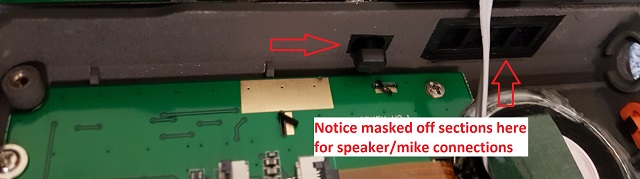
Don’t coat the rectangular plastic piece that fits over the side speaker/mic connectors, these must be left ’floating’ from ground. This nickel coating will give an extra 10dB worth of shielding to the back side of the main PCB, which results in a ’cleaner’ receiver, especially in an area of moderate RF fields: weaker signals are less distorted and disturbed by nearby transmitters in comparison to a GD-77 without this treatment.
Chassis to PCB shielding: A good connection between the PCB earth and the chassis will ensure the best RF shielding possible.
1) Begin by removing all screws holding the PCB to the aluminium chassis, and de-solder the antenna connection from the PCB, and then lift the PCB away from the chassis.
2) Use some fine sandpaper to slightly ’rough up’ the raised areas on the chassis where it would meet the gold plated ground plane of the PCB. Give the chassis a good clean with a fine dry paint brush to remove any dust etc.
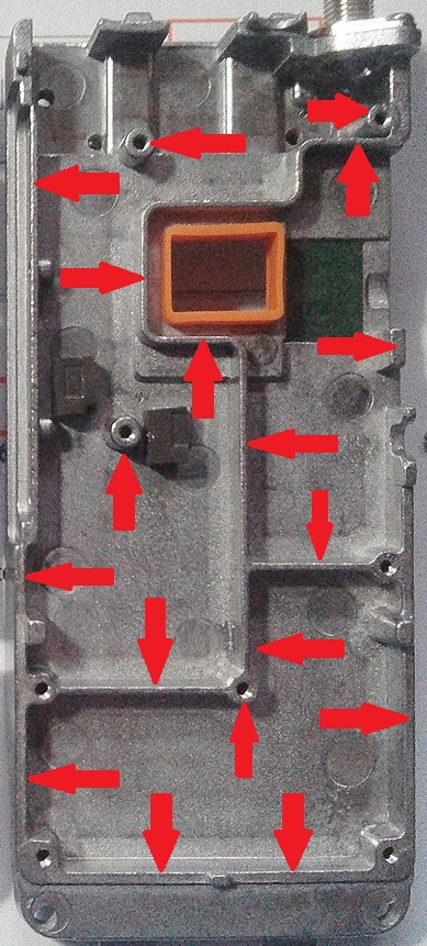
4) Replace the PCB onto the chassis, being careful to replace the little grey foam heat transfer blocks correctly, and secure the screws. Do the screws up quite firmly, but not too tight as you’ll strip the threads. This is critical for good RF shielding. Note that there’s one screw that has a flat head that goes just above the ribbon connector, all the other screws have a slightly rounded head.
5) Once the screws are all tightened down, only then should you resolder the antenna connection on the PCB.
Shielding tape to cover openings: Use some thin metallic adhesive tape to cover up any remaining openings. Be neat & precise with your tape application, you don’t want it to short out anything.
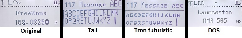
Changing display fonts on the GD-77. Advanced
(Credit to Colin G4EML, Roger VK3KYY, Jason VK7ZJA & Ronan EI4KN - the only person I know who can do complex binary math in his head like it was a second language!)
The font type used for the GD-77 display can be modified to suit your taste. You can load a larger font type (to a point) to make the display easier to read, or a cleaner font type, or jazz up your display with a quirky and unique font, perhaps even create your very own font to put that personal touch to your GD-77. The font used on the GD-77 is 8 pixels wide by 16 pixels high, in a simple bitmap format, one byte (8 bits) per line. You can download a font already in this format, or convert an existing font, or if you have the time design and create your own. There are a few fonts ready to use that you can download here:
http://members.optuszoo.com.au/jason.reilly1/GD77FontPack.zip
Here are just a few examples of some fonts in the above font pack file:
http://www.rayslogic.com/Software/RaysFontEditor/RaysFontEditor_24Aug12.zip (3.0 Mb)
To use Rays Font Editor to produce a bitmap ready for the GD-77:
1) Install your desired TTF font as a system font on your PC
2) Select Capture System Font, then select your desired font from the list
3) Select input size by point, and play around with the value to get each character fully visible. Typically the letter W is difficult to fit in 8 pixel width, try smaller point values to get the font small enough to fit the 8 pixel width. As an example, the Courier New TTF font works well if imported at 10 point size
4) Select Output character size - Change font size and enter height of 16 pixels and width of 8 pixels, and click OK
5) Examine your characters that have been imported to make sure they all fit nicely and are fully legible
6) Select Font settings, and choose character range starting at 32 and ending at 126, as those are the only characters the GD-77 needs
7) Select Export font. You want to select ’custom’, format is binary file, leave the other settings as they are. Give your font a name and save it
8) Rename the extension of your font from a .dat to .bin and you have a file that’s ready to go into the GD-77
Once you have a binary image of your desired font, you might want to use Colin’s ImageTest application to examine the fonts as they’ll appear on the GD-77 screen. Download ImageTest.exe here:
http://members.optuszoo.com.au/jason.reilly1/ImageTest.zip (15kb)
Now it’s time to write the font binary image to the GD-77. In general terms, this is done by: reading flash memory from the GD-77, saving it to your PC - it’s good to keep as a backup! - then using HxD, copy your font binary image in over the top of the location of the existing font captured from the flash memory read, and then writing back to flash memory.
You need to download Roger’s GD-77 Flash Manager from here:
Download GD-77 Flash Manager here (61kb)
Here’s a step-by-step guide for reading, editing and re-writing a font to GD-77 flash memory:
1) Turn off your GD-77, connect your USB programming cable, and put the GD-77 into the special flash read/write mode with the following power up sequence: Blue side button + green menu button + * (lock) button held down while powering up the radio. The GD-77 will appear to power up normally.
2) In Flash Manager, enter a Start address (hex) of 0, a Length (hex) of 100000, and click the Read button. This will take about 6 minutes to complete
3) Click the Save File button. This is a complete backup of your flash memory, which includes things such as RF ’soft’ alignment data and original fonts. Make several copies of this file and keep them safe. Also make another copy for you to work on in the next step
4) In HxD, open your copy of the GD-77 flash contents backup. Scroll down to address 90000
5) Still in HxD, open your desired font .bin image. HxD will open this in a new tab
6) Copy the contents of your font .bin image by highlighting the data from address 0 to 5EF, right click and select copy
7) Go back to the tab in HxD that contains your GD-77 flash contents backup. Place your cursor at address 90000 and click the mouse button to ensure that location is definitely selected. Go to the menu bar Edit and select ’paste write’. Do not select paste insert. You’ll see a bunch of text turn red - indicating you have over-written the original font data with your new font data in HxD
8) Save your file, giving it a unique name to indicate the new font
9) Back in Flash Manager now, click Open File and select the unique file name you just saved with HxD
10) Now it’s time to use Flash Manager to send this data back to the GD-77. Enter Start address (hex) of 90000, and Length (hex) of 10000. We don’t need to write the full image back, just a 64kb block of data that we did change. When you’re ready, click write. This will take about 25 seconds to write, and you might see the GD-77 display do some strange things during the write - this is normal and goes away
11) The GD-77 will reset and you’ll have your new font installed
Inverting the LCD display on the GD-77 (turn it into a GD-77BB) Advanced
(Credit to Dennis DB2OE)
The usual GD-77 LCD display is black lettering on a light background. There is also another version called the GD-77BB that has the display inverted with white letting against a black background. You can change the LCD display of the regular GD-77 yourself if you want with the instructions Dennis has put into the following pdf document:
http://members.optuszoo.com.au/jason.reilly1/radioddity_GD-77_LCD_INVERSION.zip (281kb)
GD-77: Some general technical information
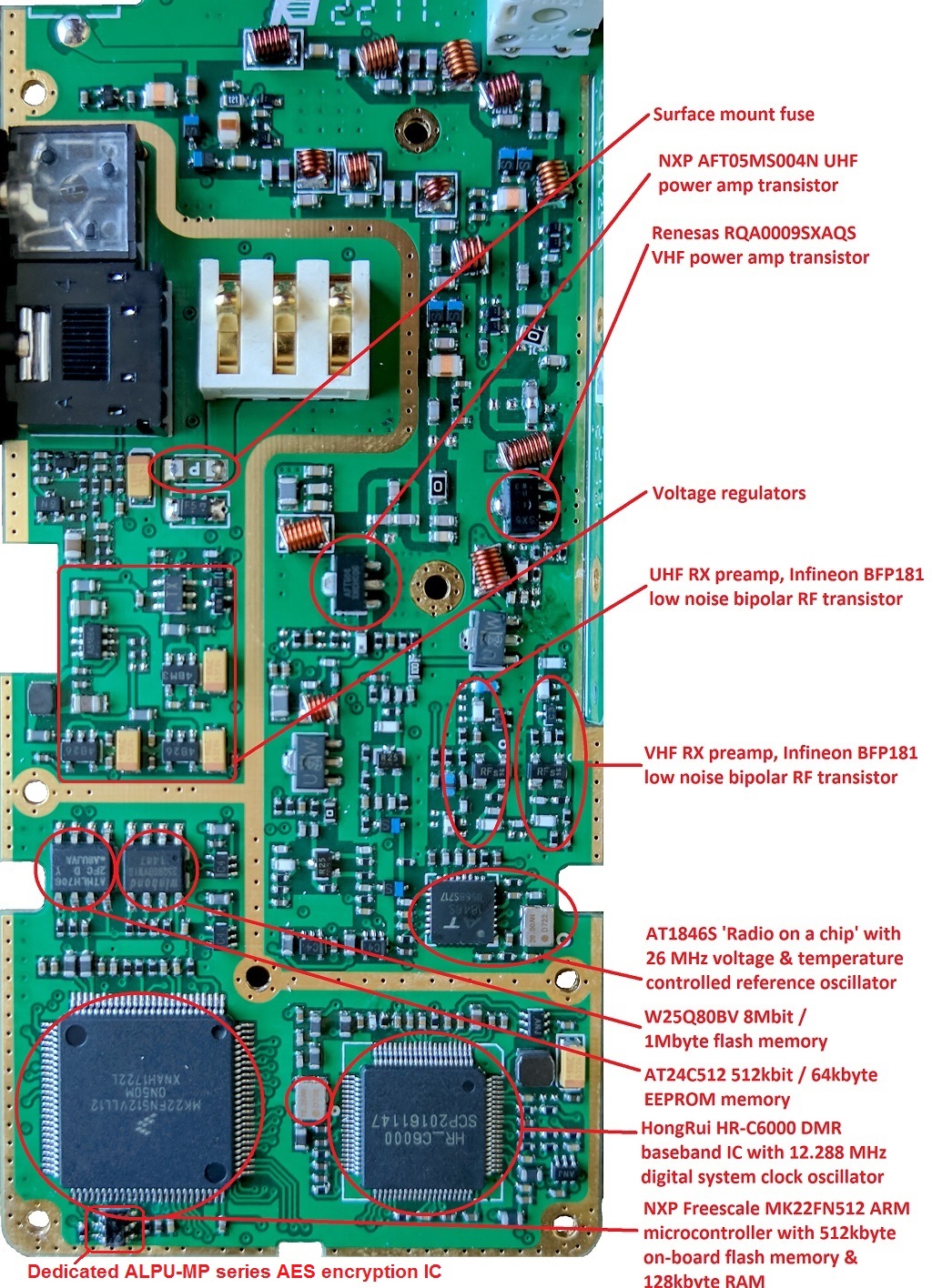
Major internal components:
MCU: NXP / Freescale MK22FN512VLL12 ARM micro controller. 512Kbyte on-board flash for operating firmware & bootloader, and 128Kbyte RAM.
DMR baseband: HongRui Comm HR_C6000. (however AMBE2+ vocoding is done in software, in the MCU)
Digital system clock: 12.288 MHz voltage & temperature controlled oscillator
8Mbit (1Mbyte) FLASH: Winbond 25Q80BVSNIG - serial FLASH 8Mbit (1Mbyte). Stores upper half of codeplug, DMR ID data, LCD display fonts, RF alignment data.
EEPROM (serial): Atmel AT24C512C (2FC marking) serial EEPROM 512kbit (64k byte). Stores lower half of codeplug.
ALPU-MP series 128 bit Advanced Encryption Standard (AES) dedicated encryption & decryption IC
RF "radio on a chip" AT1846S with 26.00 MHz reference oscillator. Handles all receive including mixer, IF amp, IF filtering, FM demod, TX synthesis, TX buffer, DTMF & tone generation, CTCSS / DCS generation & detection.
UHF RF PA: AFT504 (NXP AFT05MS004N)
VHF RF PA: SX5 (Renesis RQA0009)
AF PA: LM4951
RF front end amps, both VHF & UHF: RFs (BFP181) Infineon low noise wideband silicon bipolar RF transistor. NF=0.9dB, power gain 21dB, transducer gain 17.5dB @ 900 MHz
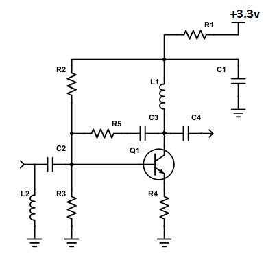
General arrangement of the RF preamps, both for VHF & UHF:
(Component designations are arbitrary and do not correspond to anything)
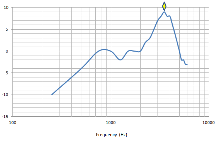
Courtesy of Paul K8PD, he tested the GD-77 audio response with a Rohde & Schwarz CMU 200, and found out why it has such crisp sounding audio - a very strong peak at 3.5 kHz is seen.
FCC Part 90 approval information:
The FCC has documented quite a bit of interesting technical information regarding the GD-77 and it’s Part 90 approval. You can find internal photographs, test reports, SAR radiation exposure limit testing reports and more. Visit the FCC report page at:
https://fccid.io/2AN62-GD77
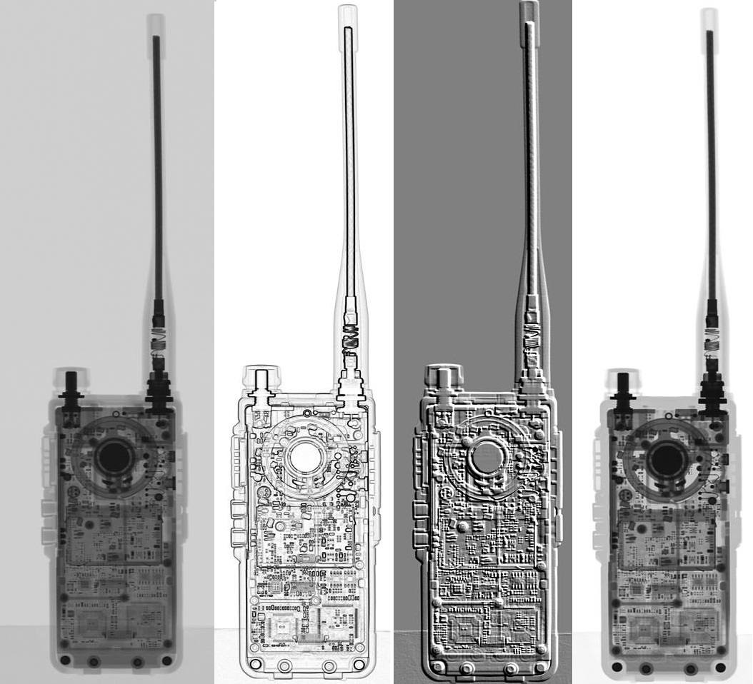
Another look inside the GD-77
With thanks to Ingo DB4BIN, we have some fascinating X-ray images of the GD-77. Very interesting, thanks Ingo!
GD-77 external flash W25Q80BV memory map:
| Address in flash | Contents |
|---|---|
| 00000-0FFFF | Shadow of EEPROM, typically empty |
| 10000-2FFFF | Copies of old codeplugs & alignment data |
| 30000-4FFFF | DMR ID data as loaded by ActiveClient.exe |
| 50000-7AFFF | Copies of old codeplugs & alignment data |
| 7B000-8EE9F | Second half of active codeplug |
| 8EEA0-8EFFF | Empty |
| 8F000-8F0DF | Active RF ’soft’ alignment data |
| 8F0E0-8FFFF | Usually empty, sometimes backup of alignment data |
| 90000-905FF | 8x8 bitmapped English characters for GD-77 display |
| 90600-907FF | Empty |
| 90800-92B3F | 16x16 bitmapped various symbols & characters not used |
| 92B40-C793F | 16x16 bitmapped Chinese characters |
| C7940-CFFFF | Possibly residual font metadata? |
| D0000-D0001 | Vital flash data (2 bytes only) - do not change! |
| D0002-D0B2F | Repetitive test data |
| D0B30-D0B31 | Vital flash data (2 bytes only) - do not change! |
| D0B32-E93CF | Repetitive test data |
| E93D0-E93D1 | Vital flash data (2 bytes only) - do not change! |
| E93D2-FB46F | Repetitive test data |
| FB470-FDFFF | Empty |
| FE000-FE5FF | Copy of 8x8 bitmapped English characters |
| FE600-FFFFF | Empty |
The three lots of two bytes mentioned above as being ’Vital flash data’ should not be changed, otherwise access to flash memory via the SK2 & menu & * button power up sequence will be lost and the only way to recover from this is to desolder the flash memory IC and program it externally.
The only data that is critical to the operation of the GD-77 in flash memory is the DMR-ID data at 30000-4FFFF, codeplug at 7B000-8EE9F, the RF alignment data at 8F000-8F0DF, the font data at 90000-905FF, and the three lots of vital flash memory values at D0000-D0001, D0B30-D0B31 and E93D0-E93D1. All other data can be deleted or changed without problems, though it would be wise to make a backup of your flash memory contents first.
GD-77 codeplug map:
This text file details the system level settings found in the codeplug .dat file, and is valid for version 2.6.3 firmware, but should be fairly accurate for earlier or later versions of firmware.
http://members.optuszoo.com.au/jason.reilly1/GD77codeplugmap.txt
Colin G4EML has produced this PDF file that expands on the channel entries etc.
http://members.optuszoo.com.au/jason.reilly1/GD77datfileformat.pdf
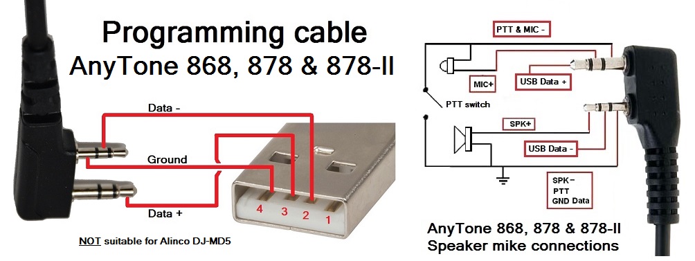
GD-77 programming cable pinout
Unlike many other Baofeng programming cables, the GD-77 cable has no electronics inside, and does not need a driver to be installed on the PC. You can even make your own spare programming cable if you wanted, using this pinout as a guide. Note that if you open up the original Radioddity programming cable, the colour code used for the wires may not conform to the USB standard. Thanks to Thorsten DC2ZU for correcting my mistake in the original diagram.
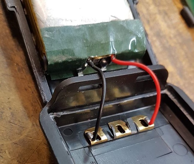
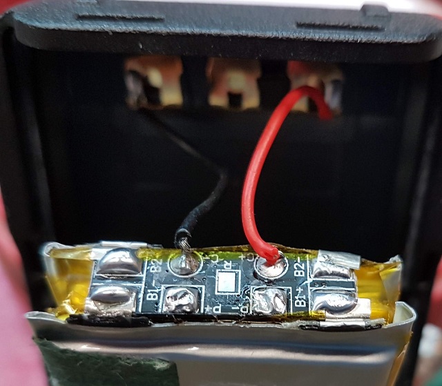
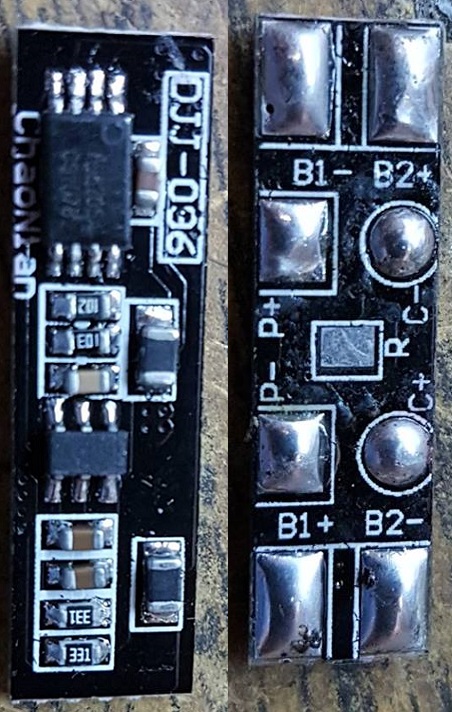
GD-77 battery pack teardown
Courtesy of Eugene UB8CJZ, we can see what is inside the GD-77 battery pack:
YouTube video tour of TYT manufacturing facility
The GD-77 is manufactured by Tytera TYT, who originally designated it the TYT MD-760. This YouTube video shows a tour of the TYT manufacturing facility, which is very likely the same facility where the GD-77 is made.
https://www.youtube.com/watch?v=R7xmHnpRCZM
Known GD-77 bug list
The following is a list of known bugs that are present in the GD-77 firmware V3.1.6. Radioddity are aware of these issues, and have promised to work on them:
1) DMR talk permit tone (General Settings > Talk Permit Tone)
In DMR digital mode, DMR talk permit tone always sounds, even if out of range of DMR radio repeater, or the repeater is busy, or the radio is denied. The talk permit tone should only sound once access to the repeater is confirmed. NB: until this feature is working properly, Radioddity have inhibited the DMR talk permit for repeater operation no matter what your CPS setting is
2) Issue with the Admit Criteria (part of each digital channel settings).
Using Colour Code Free, when the channel is not in use, the radio is allowed to TX (good)
When the opposite timeslot is in use, the radio is allowed to TX (good)
When the selected timeslot is in use for another talkgroup, the radio is NOT allowed to TX (good)
HOWEVER, when the selected timeslot is in use for the SELECTED talkgroup, the radio is still NOT allowed to TX after the transmission has ended, until the RF carrier on the frequency has dropped (bad - user is unable to reply to a transmission in their talkgroup)
3) No DMR receive when RX Group List set to none (part of each digital channel settings).
Most other DMR radios make the assumption that if RX Group is set to none, then the receive group is the same as the selected channel Contact e.g. if RX Group List = none, then RX Group is assumed to be the same as TX Contact programmed for that channel. It would be good to have the GD-77 follow this convention. Instead, the GD-77 does not do this, it must have a RX Group List programmed to hear anything.
4) Factory reset corrupts memory in GD-77 (firmware versions between & including 2.6.7 - 3.1.1 only)
Performing a factory reset (SK1 + 1 while powering on) under certain conditions causes memory corruption and results in undesired problems with the radio, such as no RF output power, signal meter inoperative etc.
Depending on the firmware in use, recovery could be as simple as downgrading to firmware version 2.6.6 and resetting, then re-loading the codeplug, or it could require some hex editing of the flash memory contents to revive it.
Audio modification for GD-77 Advanced
As standard the GD-77 has a very crisp and bright sounding receiver. Some may prefer a more mellow and smoother sounding radio - if that is you, this mod is what you want. You will need to be very good with soldering SMD components.
Since audio is subjective to each individual, here is a link to download a mp3 file which compares the unmodified vs modified audio result in both FM and DMR. You can then decide if you prefer the crisp, bright sound of the GD-77 as it is, or modify for a more smoother, mellow sound. This mod only affects RX, it makes no difference for TX.
There are four recordings of Vincent Price speaking as heard through the GD-77. First: unmodified GD-77 FM. Second: modified GD-77 FM. Third: unmodified GD-77 DMR. Last: modified GD-77 DMR. Download the GD-77 audio comparison mp3 file from TinyUpload here
Parts you will need for the modification are: 1x 1000pF SMD capacitor, 1x 47nF SMD capacitor, 1x 2.0Meg ohm or 2.2Meg ohm SMD resistor, 1x 4.7k ohm resistor. All SMD 0402 imperial size. I recommend getting a hold of five of each component, they are *tiny* and very easy to lose while working with them.
Add / change components as indicated below:
If you think the mod goes too far in taming the audio response, for a result half way between the two, alter the component changes to: added 1000pF change to 390pF, 2.0M ohm or 2.2M ohm change to 1M ohm, 4.7k ohm change to 10k ohm, and added 47nF change to 10nF.
Common GD-77 faults and their fixes Thankfully, the GD-77 hardware is quite reliable, remarkably so considering the very affordable price of a GD-77. Most problems are a result of incorrect programming of the radio. The two most common hardware problems, and how you can fix them are listed below:
Soft audio squeal at low volume. Advanced
Some (mostly early) GD-77 units are known for emitting a low audible squeal through the internal speaker at low volume settings. This is especially noticeable with a freshly charged battery, and the issue disappears as the battery drops below 8.0 volts, or when an external speaker microphone is used.
The easiest to implement fix is to remove and replace the SMD resistor on the input to the LM4951 audio PA. Change the indicated resistor from 7.5 or 10k as fitted by the factory to 15k ohm (SMD marking "153"). In this instance, a near enough substitute value is NOT acceptable, it must be 15k ohm. The SMD size is 0402, but I've used a 0603 size resistor as shown here quite successfully. This fix has been tested to be effective at all supply voltages between 6.0 to 8.7 volts (and if your battery is putting out >8.5 volts you have bigger issues at hand!) and at all volume settings.
The easiest way to remove the existing resistor is to add a some solder blobs to each end of the resistor, then lay your soldering iron tip over the resistor so it bridges both solder blobs at either end of the resistor, heating both ends up at once. The resistor will come free very quickly if done right. Then clean up the PCB lands with some solder wick. Then solder in your replacement 15k ohm resistor. A toothpick can come in handy to hold the SMD resistor in place while you solder it.
If your radio doesn't have this issue, there is no benefit to carrying out this fix. Only apply this mod if you have the problem.
Blank screen or white screen only. Moderate
If your GD-77 has a blank screen or only a white backlit background, but the rest of the radio is functioning normally (e.g. keypad beeps, receiving OK etc.) then this is a sure sign that one of the ribbon cables inside the radio has slightly come out of it’s connector, enough to stop the screen from working. All that is required is to open up the radio, and re-seat the ribbon cables - the key to a successful fix is to have the ribbon cables sitting in their connectors squarely, not at a slight angle (which is easy to do).
Referring to the picture below, the two ribbon cables are released from their connectors by the darker brown plastic ’collar’ which hinges upward away from the PCB. Use a tiny flat blade screwdriver to gently flip it up, and the ribbon cable should release right away. Give the ribbon cable contacts a quick clean with a microfibre cloth, and re-insert it squarely to the connector, and flip the dark brown collar back down to secure the ribbon cable in place. Repeat for all the other ribbon cable connectors - three in total. Reassemble the radio and your display should be working again.
It was also reported that a batch of GD-77 radios had a faulty display driver supplied to the manufacturer. Re-seating the ribbon cable won’t fix this, so if you’ve tried doing that already and it hasn’t restored your display, get in contact with the supplier of your GD-77 and (politely!) discuss the matter with them.
Low RF power output in either FM or DMR after a reset. Moderate
There were some versions of firmware that you should not use to perform a memory reset. Those versions were 2.6.7 through to 3.1.1. If you have done a reset with one of these firmware versions, sometimes the RF alignment data can be corrupted, and one symptom typically noticed is low RF output power, in either FM or DMR mode, or both together. This can be recovered by using software called Flash Manager to read your GD-77 flash memory to find an automatically created backup copy of the RF alignment data, and using that backup to replace the corrupt data.
Look towards the bottom of this page for how to do this: GD-77 Tuning, alignment & flash memory corruption recovery information
If you didn’t find what you were looking for here, take a look at my other pages:
GD-77 Tuning, alignment & flash memory corruption recovery information
GD-77 Frequently Asked Questions FAQ & answers
Absolute beginners guide to DMR
GD-77 Review
© Copyright Jason Reilly (SK), 2018-2022
nq4t.com does not claim ownership or intend to infringe any copyrights. This is mirrored here in effort to preserve the information due to the author's death.